Consultancy in structural rehabilitation
Macro-elements method – “Vulnus” and “C-Sisma”
The safety of old masonry and wood buildings is normally determined through a structural analysis of elastic models, using standard automatic calculation programmes, an offshoot of the approach used in new construction. This approach to old constructions to be rehabilitated raises various obstacles (the difficulty in visualizing the structure in terms of the elements currently used, a lack of knowledge of past alterations and of the consequent state of tension and the inelastic behaviour of the masonry).
The so-called “macro-elements” alternative approach is of interest for determining the seismic safety of buildings of this type - as confirmed by observations of buildings affected by recent earthquakes in Italy. Macro-elements are the construction elements characterized by a particular seismic behaviour, whose equilibrium is studied using cinematic models, within the plane and outside the plane. Using this approach makes it possible to calculate, for each one, a “collapse coefficient”, “c”, representing the multiplier of the masses involved that may lead the element’s collapse. This approach applies two complementary procedures: The “Vulnus” and the “C-Sisma.”
Through the “Vulnus” procedure, various mechanisms may be combined for an overall analysis of the seismic vulnerability of buildings that are sufficiently regular (in layout and elevation) and of limited height, taking into consideration the type of connection between the structural elements. The procedure provides two indices, I1 and I2, representing the limit coefficients respectively in the plane and outside the plane. Moreover, based on the specific diagnostics information (collected using a detailed form), a I3 index may be obtained for an overall assessment of the vulnerability, fragility curves and damage scenarios in accordance with classification EMS98.
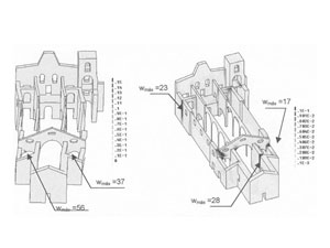
The “C-Sisma” procedure selects the building’s most significant macro-elements, applies a number of different isolated cinematic collapse mechanisms, within the plane and outside the plane, indicates the lowest seismic coefficient, corresponding to the most fragile mechanism from among those that may occur, and is capable of performing the evaluation in accordance with the regulatory requirements.
Discrete element method
One of the various ways of modelling stone masonry structures consists of the “Discrete Element Method” or the “Blocks Method” where it is admitted that the system’s deformability is totally represented by the discontinuity surfaces. It is thus accepted that the elements (blocks) are non-deformable, which is close to reality.
Finite element method
Oz is able to supply structural modelling services using the powerful "Diana" software developed by TNO.
Oz’s software, based on the method of finite elements, allows it to perform statistical and dynamic analyses, in the linear or non-linear form, a particularly versatile and appropriate method for complex structures such as old masonry buildings.
Given its in-depth knowledge about the pathologies and rehabilitation of recent and old constructions, the company is able to provide its clients, not only the analytical model, but also a number of recommendations about the strategies and techniques for repair and reinforcement interventions.
These services are of interest, not only to users or top managers responsible for the constructions in question, but also to the design departments in charge of designing and planning the rehabilitation interventions.
Examples:
|
|
|||||||||||||
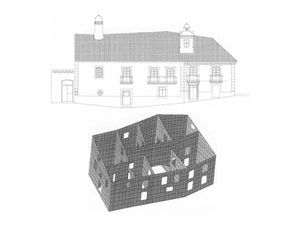
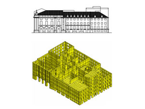
| Figure 1 - Casa do Lanternim, Mértola: view of the main elevation and model of finite elements adopted for the overall analysis. | Figure 2 - Quarteirão do Martinho da Arcada, Lisbon: view of the main façade and model of finite elements adopted for the overall analysis. |
|
|
|||||||||||||
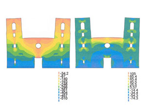
| Figure 3 - Linear plane analysis of Santuário de Santo Cristo in Outeiro, Bragança: representation under the deformed structure of the maximum and minimum principal tensions (kPa). | Figure 4 - São Francisco Church, in Horta: principal compression tensions (kPa) for vertical actions (north elevation and perspective). |
|
|||||||||
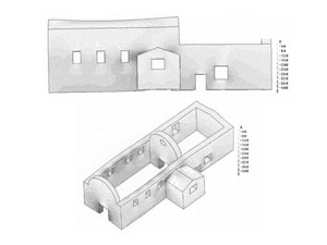
| Figure 5 - São Francisco Church, in Horta: cracking for the seism +Y for 86% of the anticipated seismic action, considering the diaphragm effect of the roofing (representation of the maximum principal extensions). |